Analysis of the Contributing Factors to Wellbore Collapse in Shallow Water Flow Formations for Deepwater Drilling
-
摘要:
为了定量评价和防治浅水流对深水钻井的危害,进行了浅水流地层井眼坍塌影响因素分析。基于流固耦合理论建立了浅水流地层井眼稳定理论模型,并分别根据Mohr-Coulomb 准则和最大拉应力准则判断砂体的剪切和拉伸破坏,分析了各因素对井周最大破坏半径及砂体临界超压的影响。计算分析发现:超压将导致浅水流地层发生破坏,随着超压增大,其最大破坏半径随之快速增至大;水平有效地应力与垂直有效地应力的比值(K0)越大,砂体埋深越大,浅水流地层越不容易发生破坏;砂体内摩擦角越大,砂体越稳定;井周最大破坏半径随着钻井液密度升高呈线性递减;浅水流地层存在临界超压,砂体埋深、强度和K0越大,临界超压越大。研究结果表明,浅水流地层井眼坍塌的风险较大,井周破坏程度与超压、地应力、砂体埋深、钻井液密度和内摩擦角等因素有关,当砂体中的超压超过临界值时,整个砂体都将处于不稳定状态,而提高钻井液密度有利于浅水流地层的稳定。
Abstract:In order to quantitatively evaluate and effectively prevent the damage of shallow water flow during deep water drilling, the contributing factors of wellbore collapse in shallow water flow formations during deep water drilling were analyzed. Based on the fluid-solid coupling theory, the theoretical model of wellbore stability in shallow water flow formation was established. Then they determined the shear and tensile damages of the sand body by the Mohr-Coulomb and maximum tensile stress criteria respectively, as well as analyzed the influence of each factor on maximum damage radius and sand body critical overpressure. The calculation and analysis found that the overpressure would lead to the damage of shallow water flow formation, the maximum damage radius increased rapidly with the increase of overpressure. The greater the ratio of effective horizontal geostress to effective vertical geostress (K0 ), and the greater the burial depth of sand body, and the less likely the shallow water flow formation is to be damaged; the larger the internal friction angle in the sand body, the more stable the sand body. Likewise, the smaller the internal friction angle, the more significant impact will be. The maximum damage radius around wellbore linearly decreases with the increase of drilling fluid density. There is a relations between critical overpressure found in the shallow water flow. The larger the burial depth, strength and K0 of sand body, the larger the critical overpressure. The results showed that the risk of wellbore collapse in shallow water flow formation was high. Further, the damage degree around wellbore was related to such factors as overpressure, geostress, sand body depth, drilling fluid density, internal friction angle, etc. When the critical overpressure is exceeded, the entire sand body will be in an unstable state, and the increase of drilling fluid density will be conducive to the wellbore stability in the shallow water flow formation.
-
浅水流是深水钻井中普遍存在的一种地质灾害[1]。它是一种浅层超压未固结砂体,通常存在于海底以下300.00~1 000.00 m的深度范围内[2],渗透率一般为1~10 D,孔隙度可达40%,在全球各大深水油气开发区(如墨西哥湾、西非、巴西等海域)均有分布[3–4],特别是墨西哥湾[5],70%的油气井都钻遇了浅水流。一口井可能钻遇多层浅水流砂层,会造成很大的经济损失,M. W. Alberty等人[6]对墨西哥湾可能出现浅水流的106口深水井的钻井费用进行了统计,用于预防和处理浅水流相关事故的总费用高达1.75亿美元,平均每口井的费用约为160万美元。
浅水流对深水钻井的危害主要表现为:在高孔隙压力驱动下,高速砂水流造成井眼坍塌、井涌甚至井喷;浅水流地层的坍塌和固井时砂水流窜入水泥浆增加了固井难度,导致固井质量较差[7];砂水流冲蚀管柱等[8]。针对深水钻井浅水流问题,前人进行了大量研究工作,但多数研究集中在利用振幅、纵横波速度比、波阻抗等地震参数识别浅水流[9–13],关于浅水流对钻井危害的定量化研究还很少。任韶然等人[14]研究了不同压力系数、砂体大小和渗透率下的浅水流流体喷出速率对钻井的影响,但是没有考虑浅水流层位井眼坍塌的问题。然而,浅水流地层的超压和砂体本身的非固结性,可能会造成较为严重的井眼坍塌等复杂问题或井下故障,因此有必要对浅水流地层的坍塌风险及其影响因素进行系统分析。为此,笔者基于流固耦合理论,建立了浅水流地层井眼稳定理论模型,并利用有限元方法求取该模型的解,分析了影响井周最大破坏半径和临界超压的因素,以期为浅水流危害的评价和防治提供一定的理论依据。
1. 浅水流地层井眼稳定理论模型
浅水流层为未固结砂体,钻出井眼后,砂体在孔隙水的快速渗流作用下可能发生渗透破坏形成流砂[15],进而导致井眼垮塌。因此,浅水流地层的井眼失稳问题是典型的流固耦合问题,可以借助多孔介质流固耦合模型进行研究。
1.1 假设条件
浅水流地层的坍塌涉及孔隙水的渗流和未固结砂体固体骨架变形破坏2个过程,因此流固耦合模型应同时考虑流体渗透和应力对砂体破坏的影响。为建立描述这2种作用的流固耦合模型,作出以下假设:1)地层处于完全饱和状态,即认为地层由固体骨架和孔隙水两相组成;2)不考虑钻进过程,即整个砂体被瞬间打开;3)沉积物和砂体为各向均匀同性弹性多孔介质;4)孔隙水和固相颗粒不可压缩,流体渗流符合达西定律;5)未固结砂体的固相颗粒之间仅存在摩擦力,即抗拉强度和黏聚力为0 MPa;6)水平方向为均匀地应力。
1.2 控制方程
控制方程主要包括力学平衡方程、渗流方程、几何方程、本构方程和破坏准则。
1.2.1 力学平衡方程
以压应力为正,拉应力为负,根据Terzaghi有效应力原理,可以用有效应力表示饱和多孔介质的力学平衡方程[16]:
∂(σ′ij+δijp)∂xj−ρgi=0 (1) 其中ρ=(1−n)ρs+nρw (2) 式中:
σ′ij 为有效应力张量,Pa;δij 为Kronecker符号;p 为孔隙压力,Pa;ρ 为沉积物的湿密度,kg/m3;ρs 和ρw 分别为地层固体颗粒和孔隙水的密度,kg/m3;n 为孔隙度;gi 为重力加速度的第i个分量,m/s2。1.2.2 流体渗流方程
由于已假设孔隙水和固相颗粒不可压缩,故地层体积的改变量等于流体流入流出的体积与源汇项之和,结合孔隙流体本构方程可得如下渗流方程:
−qi,i+qv=1M∂p∂t+∂εv∂t (3) 其中qi,i=∂vi∂xi (4) 式中:
vi 为渗流速度张量(可由达西定律得到),m/s;xi为第i个坐标分量,m;qv 为沉积物中的源汇项,1/s;M 为Biot模量,Pa;εv 为体积应变;t 为时间,s。1.2.3 破坏准则
当砂体有效应力小于0或者剪切力超过剪切强度时,即认为砂体在渗透力的作用下发生破坏[17],从而引发井眼坍塌。这里采用Mohr-Coulomb准则判断砂体是否发生剪切破坏,即:
σ′1−σ′3tan2(45∘+φ2)⩾ (5) 式中:
\sigma _1^{'} 和\sigma _3^{'} 分别为最大主应力和最小主应力,Pa;\varphi 为内摩擦角,(°)。当最大有效应力小于0时,砂体即发生拉伸破坏,即:
\sigma _1^{'} \leqslant 0 (6) 控制方程中的几何方程可根据小应变假设下的应变–位移关系式得到,而本构方程则采用多孔介质弹性模型描述。
2. 模型的数值求解
由于很难求得浅水流地层井眼稳定理论模型的解析解,因此利用有限元方法求取该理论模型的数值解,将得到的浅水流地层井眼附近的应力场代入破坏准则后即可分析井周破坏情况。
2.1 地层实体模型
对于各向同性地层,当水平地应力相等时,井眼的力学失稳为轴对称问题。图1(a)所示为过井眼轴线的地层垂直剖面。根据浅水流砂体超压形成的必要条件[18]可知,砂体周围应存在低渗透的沉积层,故几何模型中超压砂体的上下和左右各分布一低渗透沉积层,上部的低渗透沉积层及其以上直至海底为正常压实的上覆沉积层,下部的低渗透沉积层及其以下地层也是正常压实的沉积层,井眼直径为660.4 mm,整个模型的厚度为1 000.00 m,宽度为120.00 m,足以消除边界效应的影响。图1(b)所示为实际计算时利用轴对称建立的有限元实体模型。
![]() 图 1 地层垂直剖面及相应的有限元实体模型Figure 1. Stratigraphic vertical section and corresponding solid model
图 1 地层垂直剖面及相应的有限元实体模型Figure 1. Stratigraphic vertical section and corresponding solid model2.2 单元划分及模型计算参数
为了更加准确地模拟井眼附近的应力分布和渗流情况,并缩短计算时间和降低内存占用,近井处的网格采用自外边界向内逐渐加密的方法进行划分,井壁处网格径向长度为0.01 m;超压砂体也进行网格加密,在垂向上采用更小的网格,网格厚度为0.05 m,整个模型共包含129 920个二阶四边形轴对称单元。
模型参数:水深2 000.00 m,海水密度1.035 g/cm3,黏度1.0 mPa·s;浅层采用海水钻进,沉积层密度均为2.0 g/cm3,上覆和下伏正常压实砂体的渗透率为0.1 D,孔隙度为0.25。浅水流地层为未固结疏松砂体,其渗透率可达几达西,孔隙度可达40%甚至更高[19],因此浅水流砂体的孔隙度取0.3~0.4,渗透率取1~3 D,砂体密度取2.5 g/cm3。为维持砂体超压,砂体周围盖层多为黏土类细粒沉积物,其渗透系数一般为1.0×10–6~1.0×10–9 cm/s[20],故盖层渗透率取0.1 mD,孔隙度取0.02。上、下低渗透层的厚度为5.00 m,各个沉积层均不考虑渗透率和孔隙度的变化。砂体上、下地层的弹性模量为200 MPa,泊松比为0.35;砂体的弹性模量为500 MPa,泊松比为0.2,内摩擦角按典型砂土材料取20°~40°,孔隙水压缩系数为4.5×10⁻¹⁰ Pa–1,Biot系数为1.0。
2.3 初始条件和边界条件
地层有限元实体模型的初始有效地应力为:
{S_{\rm{v}}} = - (\rho - {\rho _{\rm{w}}})gz{K_0} (7) {S_{\rm{h}}} = {K_0}{S_{\rm{v}}} (8) 式中:
{S_{\rm{v}}} 和{S_{\rm{h}}} 分别为垂直和水平有效主应力,Pa;z 为海底以下的地层深度,m;{K_0} 为侧压力系数,为水平与垂直有效主应力的比值。模型的初始孔隙压力:
p = {\rho _{\rm{w}}}g(z + H) (9) 式中:H为海水深度,m。
在模型上表面施加表面力以模拟受到的上覆海水重力,表面力大小等于海底静水压力,对整个模型施加垂直向下的体积力γ=ρg来模拟沉积物自身重力,井壁施加钻井液液柱压力。
模型上表面为自由边界,孔隙压力等于海底静水压力,即:
{\left. p \right|_{z = 0}} = {\rho _{\rm{w}}}gH (10) 模型底部与侧面为非渗透边界,即边界处渗流速度为0,且限制底部和侧面的法向位移。
3. 井周最大破坏半径的影响因素
3.1 地层压力
砂体埋深600.00 m、厚度20.00 m、直径50.00 m、内摩擦角30°、砂体孔隙度0.3、渗透率1.0 D及K0=0.6时,不同超压下井周的破坏情况如图2所示。由于破坏区域相对于整个模型较小,为了清晰地展示井周破坏情况,只展示了井眼附近区域(图2中,深红色区域为剪切和拉伸破坏区域,绿色区域为未破坏区域)。
![]() 图 2 不同超压下浅水流地层井周破坏情况Figure 2. The damage around wellbore in shallow water flow formation under different overpressures
图 2 不同超压下浅水流地层井周破坏情况Figure 2. The damage around wellbore in shallow water flow formation under different overpressures由图2可知,随着超压增大,浅水流地层井周破坏区域逐渐增大。这些破坏区域的未固结砂体在超压流体的渗流作用下极易发生坍塌。例如,超压为0.5 MPa时,井周破坏半径为0.53 m;超压增至2.5 MPa时,井周破坏半径增至1.38 m。
地层压力对井周破坏的影响较大,而井周破坏区域的大小可以用破坏区域的半径表征,不过由于上覆和下伏地层以及地应力的影响,井眼钻成后浅水流地层在垂向上的应力分布存在差异,导致井周破坏情况在垂向上也略有不同,因此笔者采用最大破坏半径表征井周破坏区域的大小。由图2可知,随着砂体超压增大,砂体有效应力逐渐减小,砂体被钻开后更容易发生破坏,因而井周破坏区域不断增大,且超压对砂体破坏区域大小的影响也越来越显著,如图3所示。
![]() 图 3 不同超压下的井周最大破坏半径Figure 3. The maximum damage radius around wellbore under different overpressures
图 3 不同超压下的井周最大破坏半径Figure 3. The maximum damage radius around wellbore under different overpressures对最大破坏半径和超压进行非线性拟合,可以得到两者之间的函数关系:
{R_{\rm{f}}} = \frac{A}{{B - \Delta p}} + C (11) 式中:
{R_{\rm{f}}} 为最大破坏半径,m;\Delta p 为超压,MPa;A,B和C为拟合常数,本例中取A=0.652 3,B=3.160 0,C=0.333 2。由式(11)可以看出,当
\Delta p 接近B 时{R_{\rm{f}}} 快速增大,因此可将B 定义为临界超压。当砂体超压达到临界超压后,整个砂体在被钻开的瞬间处于不稳定状态。本例中,临界超压的计算结果为3.017 MPa。3.2 钻井液密度
砂体超压为2.5 MPa时,井周最大破坏半径随钻井液密度的变化如图4所示。
![]() 图 4 井周最大破坏半径随钻井液密度的变化Figure 4. Variation of the maximum damage radius around wellbore with the density of drilling fluid
图 4 井周最大破坏半径随钻井液密度的变化Figure 4. Variation of the maximum damage radius around wellbore with the density of drilling fluid从图4可以看出,随着钻井液密度增大,井周最大破坏半径基本呈线性递减趋势。分析认为,这是由于井壁处的径向有效应力增大造成的。另外,从图4也可看出,当钻井液密度从1.035 g/cm3提高至1.130 g/cm3时,砂体埋深为600 m时的井周最大破坏半径由1.380 m减至0.731 m,砂体埋深为500.00 m时的井周最大破坏半径由4.565 m减至1.960 m,由此可知,钻遇浅水流地层时适当地提高钻井液密度,可显著减小浅水流地层的井周破坏面积。
3.3 砂体埋深
埋深不同,相应的上覆岩层压力和水平地应力也会不同,因此即使在同样大小的超压下,浅水流地层井周破坏区域的大小也不一样。K0=0.60和K0=0.65时,不同砂体埋深处的浅水流地层在超压1.0 MPa时的井周最大破坏半径如图5所示。
![]() 图 5 不同砂体中部埋藏深度下的井周最大破坏半径Figure 5. The maximum damage radius around wellbore at middle depth under the different sand body
图 5 不同砂体中部埋藏深度下的井周最大破坏半径Figure 5. The maximum damage radius around wellbore at middle depth under the different sand body由图5可知:砂体埋藏越深,井周破坏区域的半径越大;砂体埋藏越浅,埋深对最大破坏半径的影响越显著。分析认为,这是由于原地应力随埋深减小导致的。砂体埋藏较浅时,同样的孔隙压力下砂体中的有效地应力降低,砂体更容易发生剪切或拉伸破坏,说明超压砂体埋藏越浅,钻遇砂体时越容易发生大规模井眼坍塌,浅水流的危害程度越大。
3.4 侧压力系数K0
砂体埋深为500.00 m,不同K0时浅水流地层井周最大破坏半径随超压的变化如图6所示。
![]() 图 6 不同K0下浅水流地层的井周最大破坏半径随超压大小的变化Figure 6. The variation of the maximum damage radius around wellbore in the shallow water flow formation with the overpressure under different K0
图 6 不同K0下浅水流地层的井周最大破坏半径随超压大小的变化Figure 6. The variation of the maximum damage radius around wellbore in the shallow water flow formation with the overpressure under different K0从图6可以看出,K0越大,井周破坏区域的最大半径越小。分析认为,这是因为当K0增大时,砂体水平地应力也相应增大,同样孔隙压力下的井周有效应力升高,砂体的有效应力摩尔圆向右移动,此时井周不易发生破坏。从图6也可以看出,超压越大,不同K0对应的井周破坏区域相差越大,例如:超压为1.0 MPa时,K0=0.65和0.55时井周破坏区域的最大半径分别为0.594和0.778 m,两者相差0.184 m;而当超压为2.0 MPa时,K0=0.65和0.55时井周破坏区域的最大半径分别为0.980和2.316 m,两者相差1.336 m,相差更大。
3.5 内摩擦角
K0=0.60、埋深500.00 m浅水流地层在不同内摩擦角下的井周破坏区域最大半径如图7所示。
![]() 图 7 不同内摩擦角下的浅水流地层井周最大破坏半径Figure 7. The maximum damage radius around wellbore in the shallow water flow formation under different internal friction angles
图 7 不同内摩擦角下的浅水流地层井周最大破坏半径Figure 7. The maximum damage radius around wellbore in the shallow water flow formation under different internal friction angles由图7可知,内摩擦角对浅水流地层井周破坏区域的影响很大,内摩擦角越大,砂体强度越大,破坏区域越小,且超压越大、内摩擦角越小时,影响越明显。
4. 砂体的临界超压及其影响因素
当超压高于临界超压
{p_{\rm{c}}} 后,由于整个砂体的有效应力非常低,在砂体被钻开的瞬间,整个砂体都处于不稳定状态,钻遇此类超压砂体将非常危险。而计算表明,砂体临界超压与砂体埋深、内摩擦角及地应力有关。不同内摩擦角、不同K0条件下,砂体临界超压随砂体埋深的变化曲线如图8所示。![]() 图 8 不同内摩擦角和K0时临界超压随砂体埋深的变化Figure 8. Variation curves of critical overpressure with sand body burial depth under different internal friction angles and K0
图 8 不同内摩擦角和K0时临界超压随砂体埋深的变化Figure 8. Variation curves of critical overpressure with sand body burial depth under different internal friction angles and K0从图8可以看出,临界超压随着砂体埋深增大呈线性增大。分析认为,这是由于砂体埋深增大,导致砂体所受的上覆岩层压力和水平有效地应力均有所升高,有效应力莫尔圆右移,从而提高了砂体抵抗渗透剪切破坏的能力。临界超压
{p_{\rm{c}}} 与砂体埋深z的关系可用以下线性方程描述:1)内摩擦角为30°、K0=0.65时,
{p_{\rm{c}}} = 0.005\;8z - 0.019\;6{\kern 1pt} {\kern 1pt} {\kern 1pt} {\kern 1pt} {\kern 1pt} {\kern 1pt} {\kern 1pt} {\kern 1pt} {\kern 1pt} {\kern 1pt} {\kern 1pt} {\kern 1pt} {\kern 1pt}({R^2} = 0.998\;6) ;2)内摩擦角为30°、K0=0.60时,
{p_{\rm{c}}} = 0.005\;0z + 0.004\;1{\kern 1pt} {\kern 1pt} {\kern 1pt} {\kern 1pt} {\kern 1pt} {\kern 1pt} {\kern 1pt} {\kern 1pt} {\kern 1pt} {\kern 1pt} {\kern 1pt} {\kern 1pt} {\kern 1pt}({R^2} = 0.997\;9) ;3)内摩擦角为36°、K0=0.65时,
{p_{\rm{c}}} = 0.006\;2z + 0.001\;6{\kern 1pt} {\kern 1pt} {\kern 1pt} {\kern 1pt} {\kern 1pt} {\kern 1pt} {\kern 1pt} {\kern 1pt} {\kern 1pt} {\kern 1pt} {\kern 1pt} {\kern 1pt} {\kern 1pt}({R^2} = 0.994\;9) ;4)内摩擦角为36°、K0=0.60时,
{p_{\rm{c}}} = 0.005\;6z - 0.018\;1{\kern 1pt} {\kern 1pt} {\kern 1pt} {\kern 1pt} {\kern 1pt} {\kern 1pt} {\kern 1pt} {\kern 1pt} {\kern 1pt} {\kern 1pt} {\kern 1pt} {\kern 1pt} {\kern 1pt}({R^2} = 0.999\;2) 。不同砂体埋深、不同K0条件下,临界超压随砂体内摩擦角的变化曲线如图9所示。
![]() 图 9 不同埋深和K0时临界超压随砂体内摩擦角的变化Figure 9. Variation curves of critical overpressure with the internal friction angle of sand body under different burial depths and K0
图 9 不同埋深和K0时临界超压随砂体内摩擦角的变化Figure 9. Variation curves of critical overpressure with the internal friction angle of sand body under different burial depths and K0由图9可知,内摩擦角增大,砂体强度提高,因此随着砂体内摩擦角增大,临界超压逐渐增大;且内摩擦角越小、K0越小,砂体埋深越大,内摩擦角对临界超压的影响越大。临界超压
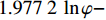
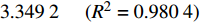
{p_{\rm{c}}} 与内摩擦角φ的关系可用以下对数方程描述:1)埋深为600.00 m、K0=0.65时,
{p_{\rm{c}}} = 1.977\;2\;\ln \varphi - 3.349\;2{\kern 1pt} {\kern 1pt} {\kern 1pt} {\kern 1pt} {\kern 1pt} {\kern 1pt} {\kern 1pt} {\kern 1pt} {\kern 1pt} {\kern 1pt} {\kern 1pt} {\kern 1pt} {\kern 1pt}({R^2} = 0.980\;4) ;2)埋深为600.00 m、K0=0.60时,
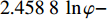
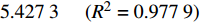
{p_{\rm{c}}} = 2.458\;8\;\ln \varphi - 5.427\;3{\kern 1pt} {\kern 1pt} {\kern 1pt} {\kern 1pt} {\kern 1pt} {\kern 1pt} {\kern 1pt} {\kern 1pt} {\kern 1pt} {\kern 1pt} {\kern 1pt} {\kern 1pt} {\kern 1pt}({R^2} = 0.977\;9) ;3)埋深为500.00 m、K0=0.65时,
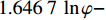
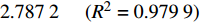
{p_{\rm{c}}} = 1.646\;7\;\ln \varphi - 2.787\;2{\kern 1pt} {\kern 1pt} {\kern 1pt} {\kern 1pt} {\kern 1pt} {\kern 1pt} {\kern 1pt} {\kern 1pt} {\kern 1pt} {\kern 1pt} {\kern 1pt} {\kern 1pt} {\kern 1pt} ({R^2} = 0.979\;9) ;4)埋深为500.00 m、K0=0.60时,
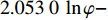
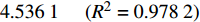
{p_{\rm{c}}} = 2.053\;0\;\ln \varphi - 4.536\;1{\kern 1pt} {\kern 1pt} {\kern 1pt} {\kern 1pt} {\kern 1pt} {\kern 1pt} {\kern 1pt} {\kern 1pt} {\kern 1pt} {\kern 1pt} {\kern 1pt} {\kern 1pt} {\kern 1pt} ({R^2} = 0.978\;2) 。初始地应力也会对临界超压产生影响,可以用K0表征初始水平地应力与上覆岩层压力的关系。不同砂体埋深、不同内摩擦角条件下,砂体临界超压随K0的变化曲线如图10所示。
![]() 图 10 不同砂体埋深和内摩擦角时临界超压随K0的变化Figure 10. Variation curves of critical overpressure with K0 under different burial depths and internal friction angles in sand bodies
图 10 不同砂体埋深和内摩擦角时临界超压随K0的变化Figure 10. Variation curves of critical overpressure with K0 under different burial depths and internal friction angles in sand bodies从图10可以看出,当上覆岩层压力不变时,随着K0增大,初始水平地应力随之增大,临界超压不断增大,且K0越小、内摩擦角越小、埋深越大,初始水平地应力对临界超压的影响越显著。数据拟合发现,
{p_{\rm{c}}} 和K0之间大致符合以下对数关系:1)埋深为600.00 m、内摩擦角为30°时,
{p_{\rm{c}}} = 5.250\;0\;\ln {K_0} + 5.698\;6{\kern 1pt} {\kern 1pt} {\kern 1pt} {\kern 1pt} {\kern 1pt} {\kern 1pt} {\kern 1pt} {\kern 1pt} {\kern 1pt} {\kern 1pt} {\kern 1pt} {\kern 1pt} {\kern 1pt} ({R^2} = 0.990\;9) ;2)埋深为600.00 m、内摩擦角为36°时,
{p_{\rm{c}}} = 4.370\;4\;\ln {K_0} + 5.606\;8{\kern 1pt} {\kern 1pt} {\kern 1pt} {\kern 1pt} {\kern 1pt} {\kern 1pt} {\kern 1pt} {\kern 1pt} {\kern 1pt} {\kern 1pt} {\kern 1pt} {\kern 1pt} {\kern 1pt} ({R^2} = 0.999\;7) ;3)埋深为500.00 m、内摩擦角为30°时,
{p_{\rm{c}}} = 4.371\;2\;\ln {K_0} + 4.746\;4{\kern 1pt} {\kern 1pt} {\kern 1pt} {\kern 1pt} {\kern 1pt} {\kern 1pt} {\kern 1pt} {\kern 1pt} {\kern 1pt} {\kern 1pt} {\kern 1pt} {\kern 1pt} {\kern 1pt} ({R^2} = 0.990\;8) ;4)埋深为500.00 m、内摩擦角为36°时,
{p_{\rm{c}}} = 3.658\;0\;\ln {K_0} + 4.684\;9{\kern 1pt} {\kern 1pt} {\kern 1pt} {\kern 1pt} {\kern 1pt} {\kern 1pt} {\kern 1pt} {\kern 1pt} {\kern 1pt} {\kern 1pt} {\kern 1pt} {\kern 1pt} {\kern 1pt} ({R^2} = 0.998\;9) 。分析认为,当砂体中的超压值超过临界超压时,整个砂体处于不稳定状态,因此钻遇此类浅水流砂体时必须提高钻井液密度,以尽可能平衡砂体中的孔隙压力,降低砂体的破坏程度。
5. 结论与建议
1)超压会导致浅水流地层发生破坏,井周破坏区域半径与超压、地应力、钻井液密度和内摩擦角等因素有关。超压越大,井周破坏半径越大,且随着超压增大,其影响越来越显著;水平有效地应力与垂直有效地应力的比值越大,超压砂体越不容易发生破坏;砂体内摩擦角越大,砂体强度越高;内摩擦角越小,其影响越显著;提高钻井液密度有利于超压砂体的稳定。
2)浅水流地层存在临界超压,当砂体达到临界超压后,整个砂体都处于不稳定状态,在外界扰动下有可能发生大规模井眼坍塌,而临界超压与砂体埋深、地应力和内摩擦角有关,随着埋深增大呈线性增大,随着水平有效地应力与垂直有效地应力的比值和内摩擦角增大而增大,且与二者均呈对数函数关系。
3)建立浅水流地层井眼稳定理论模型时,未考虑浅水流地层含水率等物性参数随时间的变化,也未模拟动态破坏过程以及非均匀地应力条件下的井眼坍塌风险,建议今后进行这些方面的研究。
-
![]()
图 1 地层垂直剖面及相应的有限元实体模型
Figure 1. Stratigraphic vertical section and corresponding solid model
![]()
图 2 不同超压下浅水流地层井周破坏情况
Figure 2. The damage around wellbore in shallow water flow formation under different overpressures
![]()
图 3 不同超压下的井周最大破坏半径
Figure 3. The maximum damage radius around wellbore under different overpressures
![]()
图 4 井周最大破坏半径随钻井液密度的变化
Figure 4. Variation of the maximum damage radius around wellbore with the density of drilling fluid
![]()
图 5 不同砂体中部埋藏深度下的井周最大破坏半径
Figure 5. The maximum damage radius around wellbore at middle depth under the different sand body
![]()
图 6 不同K0下浅水流地层的井周最大破坏半径随超压大小的变化
Figure 6. The variation of the maximum damage radius around wellbore in the shallow water flow formation with the overpressure under different K0
![]()
图 7 不同内摩擦角下的浅水流地层井周最大破坏半径
Figure 7. The maximum damage radius around wellbore in the shallow water flow formation under different internal friction angles
![]()
图 8 不同内摩擦角和K0时临界超压随砂体埋深的变化
Figure 8. Variation curves of critical overpressure with sand body burial depth under different internal friction angles and K0
![]()
图 9 不同埋深和K0时临界超压随砂体内摩擦角的变化
Figure 9. Variation curves of critical overpressure with the internal friction angle of sand body under different burial depths and K0
-
[1] 孙宝江, 张振楠. 南海深水钻井完井主要挑战与对策[J]. 石油钻探技术, 2015, 43(4): 1–7. SUN Baojiang, ZHANG Zhennan. Challenges and countermeasures for the drilling and completion of deepwater wells in the South China Sea[J]. Petroleum Drilling Techniques, 2015, 43(4): 1–7.
[2] CUNDIFF L W, DAUGHERTY B, MIX K. Case study: statistical risk to a drill center from shallow-water flow[J]. Journal of Petroleum Technology, 2005, 57(3): 64–67. doi: 10.2118/0305-0064-JPT
[3] BRUCE R, MCKEOWN J, SARGENT T, et al. Mitigating the shallow water flow risk at Mississippi canyon 849: a team approach[R]. OTC 15249, 2003.
[4] OSTERMEIER R M, PELLETIER J H, WINKER C D, et al. Dealing with shallow-water flow in the deepwater Gulf of Mexico[R]. OTC 11972, 2000.
[5] PUTANS V, MERKLIN L R, LEVCHENKO O V. Sediment waves and other forms as evidence of geohazards in Caspian Sea[J]. International Journal of Offshore & Polar Engineering, 2010, 20(4): 241–246.
[6] ALBERTY M W, HAFLE M E, MINGE J C, et al. Mechanisms of shallow water flows and drilling practices for intervention[J]. SPE Drilling & Completion, 1999, 14(2): 123–129.
[7] FULLER G A, BOLADO D L, HARDY F. A Gulf of Mexico case history: benefits of foamed cementing to combat a SWF[R]. SPE 128160, 2010.
[8] 叶志, 樊洪海, 张国斌, 等. 深水钻井地质灾害浅层水流问题研究[J]. 石油钻探技术, 2010, 38(6): 48–52. doi: 10.3969/j.issn.1001-0890.2010.06.011 YE Zhi, FAN Honghai, ZHANG Guobin, et al. Investigation of shallow water flow in deepwater drilling[J]. Petroleum Drilling Techniques, 2010, 38(6): 48–52. doi: 10.3969/j.issn.1001-0890.2010.06.011
[9] MALLICK S, DUTTA N C. Shallow water flow prediction using prestack waveform inversion of conventional 3D seismic data and rock modeling[J]. The Leading Edge, 2002, 21(7): 675–680. doi: 10.1190/1.1497323
[10] DENNEY D. Shallow-water-flow prediction from multicomponent seismic data[J]. Journal of Petroleum Technology, 2000, 52(7): 34–36. doi: 10.2118/0700-0034-JPT
[11] MUKERJI T, DUTTA N, PRASAD M, et al. Seismic detection and estimation of overpressure: part Ⅰ: the rock physics basis[J]. CSEG Recorder, 2002, 27(7): 34–57.
[12] ZIMMER M, PRASAD M, MAVKO G. Pressure and porosity influences on Vp-Vs ratio in unconsolidated sands[J]. The Leading Edge, 2002, 21(2): 178–183. doi: 10.1190/1.1452609
[13] 吴时国, 孙运宝, 王秀娟, 等. 南海北部深水盆地浅水流的地球物理特性及识别[J]. 地球物理学报, 2010, 53(7): 1681–1690. doi: 10.3969/j.issn.0001-5733.2010.07.019 WU Shiguo, SUN Yunbao, WANG Xiujuan, et al. Geophysical signature and detection of shallow water flow in the deepwater basin of the Northern South China Sea[J]. Chinese Journal of Geophysics, 2010, 53(7): 1681–1690. doi: 10.3969/j.issn.0001-5733.2010.07.019
[14] 任韶然, 宫智武, 张亮, 等. 南海北部陆坡浅水流评估及深水钴井防治措施[J]. 中国石油大学学报(自然科学版), 2017, 41(4): 99–106. doi: 10.3969/j.issn.1673-5005.2017.04.013 REN Shaoran, GONG Zhiwu, ZHANG Liang, et al. Shallow water flow hazard assessment in the northern slope of the South China Sea and control measures during deepwater drilling[J]. Journal of China University of Petroleum(Edition of Natural Science), 2017, 41(4): 99–106. doi: 10.3969/j.issn.1673-5005.2017.04.013
[15] 李广信, 周晓杰. 土的渗透破坏及其工程问题[J]. 工程勘察, 2004(5): 10–13, 52. LI Guangxin, ZHOU Xiaojie. Seepage failure of soil and related engineering problems[J]. Geotechnical Investigation & Surveying, 2004(5): 10–13, 52.
[16] SUN Jin, DENG Jingen, YU Baohua, et al. Model for fracture initiation and propagation pressure calculation in poorly consolidated sandstone during waterflooding[J]. Journal of Natural Gas Science and Engineering, 2015, 22: 279–291. doi: 10.1016/j.jngse.2014.12.004
[17] BENMEBAREK N, BENMEBAREK S, KASTNER R. Numerical studies of seepage failure of sand within a cofferdam[J]. Computers and Geotechnics, 2005, 32(4): 264–273. doi: 10.1016/j.compgeo.2005.03.001
[18] 孙运宝, 赵铁虎, 秦柯. 南海北部白云凹陷沉积压实作用对浅水流超压演化影响数值模拟[J]. 地球科学进展, 2014, 29(9): 1055–1064. SUN Yunbao, ZHAO Tiehu, QIN Ke. Numerical simulation of overpressure of shallow water flow in Baiyun Sag of the Northern South China Sea[J]. Advances in Earth Science, 2014, 29(9): 1055–1064.
[19] OSTERMEIER R M, PELLETIER J H, WINKER C D, et al. Trends in shallow sediment pore pressures: deepwater Gulf of Mexico[R]. SPE 67772, 2001.
[20] 陈仲颐, 周景星, 王洪瑾.土力学[M].北京: 清华大学出版社, 1994: 46-47. CHEN Zhongyi, ZHOU Jingxing, WANG Hongjin. Soil mechanics [M]. Beijing: Tsinghua University Press, 1994: 46-47.
-
期刊类型引用(4)
1. 金衍,林伯韬,高彦芳,庞惠文,郭旭洋,申屠俊杰. 油气藏相变岩石力学理论方法及应用场景. 石油勘探与开发. 2025(01): 140-150 .  百度学术
百度学术
2. 刘存革,裴健翔,欧阳敏,王大伟,孙金,吴涛,王梅. 南海北部深水井场稳定性评价. 广东石油化工学院学报. 2023(01): 1-4 . 百度学术
3. 申屠俊杰,林伯韬,陆吉. 深水浅层浅水流灾害风险评价与防灾方法研究. 石油科学通报. 2021(03): 451-464 . 百度学术
4. 李庆超,程远方,邵长春. 允许适度坍塌的水合物储层最低钻井液密度. 断块油气田. 2019(05): 657-661 . 百度学术
其他类型引用(0)


 下载:
下载:


计量
- 文章访问数: 3611
- HTML全文浏览量: 2122
- PDF下载量: 58
- 被引次数: 4