Design and Optimization of the Crawling Mechanism of Rotary Sidewall Coring Device in Shale Gas Wells
-
摘要: 为了解决页岩气井旋转式井壁取心器不能靠自重下至取心位置的问题,分析了取心器的工作要求,确定了取心器在水平井中所受阻力,设计了一种由行星齿轮、锥齿轮组合传动的旋转式井壁取心器爬行机构。建立了爬行轮正压力与各参数的函数关系、支撑臂伸出速度与各参数的函数关系;以支撑臂伸出速度和支撑臂推靠力为多目标优化函数,利用正交试验分析方法,确定了爬行臂长度、支撑臂长度、爬行臂转角和偏心距等因素的影响程度,并优化了爬行臂和支撑臂的结构尺寸。分析得到:爬行臂转角对支撑臂伸出速度和推靠力的影响最大;当爬行臂转角、爬行臂长度、偏心距和支撑臂长度分别为45°、150 mm、8 mm和140 mm时,爬行臂伸出速度和推靠力最优;爬行臂和支撑臂长度优化后,可以降低支撑臂所需推靠力,提高支撑臂伸出速度。研究认为,设计的页岩气井旋转式井壁取心器爬行机构,为井壁取心器提供了一种新的驱动方式。Abstract: With regard to the problem that the rotary sidewall coring device of shale gas wells cannot be lowered to the coring position with its own weight, the operating requirements of the coring device were analyzed, and the resistance to the coring device in the horizontal wells was determined. Then, a new crawling mechanism transmitted by planetary and bevel gears was designed for rotary sidewall coring device. The functional relationships of the positive pressure of the crawling wheel and the extension speed of the supporting arm with each parameter were established. With the extension speed and push-the-bit force of the supporting arm as the multi-objective optimization function, the order of priority of the influencing factors such as the length, rotation angle, and eccentricity of the crawling arm and the length of the supporting arm was determined through the orthogonal tests. Furthermore, the physical dimensions of the crawling arm and supporting arm were optimized. The analysis results demonstrated that the rotation angle of the crawling arm had the greatest influence on the extension speed and push-the-bit force of the supporting arm. When the rotation angle, length, and eccentricity of the crawling arm and the length of the supporting arm were 45°, 150 mm, 8 mm, and 140 mm, respectively, the extension speed and push-the-bit force of the crawling arm were optimal. The optimization of the lengths of the crawling and supporting arms facilitated the decline in the push-the-bit force needed by the supporting arm and the increase in the extension speed of the supporting arm. The crawling mechanism of the rotary sidewall coring device for shale gas wells provides a new driving method for the sidewall coring device.
-
川渝地区页岩层经历了强烈的后期改造,地质条件相对复杂,页岩分布不稳定,呈现较强的各向异性特征。对于页岩气的勘探开发,井壁取心技术是关键技术之一,页岩气水平井的水平段长达1 000~2 000 m,采用常规钻杆、连续油管难以将取心器准确下至取心位置,且钻井完井工作难度大、耗时长、费用高[1-2]。针对川渝地区页岩气水平井长水平段取心困难的问题,张宇奇[3]将井下爬行器与旋转式井壁取心器相结合,设计了一种具备爬行、定位、推靠、取心、储样和解卡等功能的旋转式井壁取心器,可完成水平井水平段、大位移定向井斜井段的取心作业;张朝界等人[4]用Solidworks软件模拟实际工况,建立了页岩气水平井和取心器的三维模型,利用ADAMS虚拟样机仿真技术,对取心器的爬行能力、过弯能力、负载能力和越障能力进行了模拟分析,结果表明均满足设计要求。
爬行机构作为旋转式井壁取心器的直接驱动装置,其性能决定了取心器能否正常完成井下取心工作。1994年,J. Hallundbæk首先设计了Welltec轮式爬行器[5],Sondex公司对轮式爬行器进行了改进,采用了2个扶正机构[6];D. Bloom等人[7]研发了Maxtrac伸缩式爬行器,M. Buyers等人[8]对其进行了改进,可以蠕动前进。2001年,沈阳工业大学研制了管道爬行器;高进伟等人[9]根据平行四边形原理设计了爬行及定心装置,解决了爬行器在井下的轴向居中问题;周劲辉等人[10]研制了水平井自扶正式电缆爬行器;唐德威等人[11]研制了井下电机驱动爬行器。适用于水平井的爬行器以伸缩式爬行器和轮式爬行器为主,伸缩式爬行器的负载大,但爬行速度较慢;轮式爬行器的爬行速度快,但牵引力较小,仅能完成测井工具的运输,无法携带大段岩心,不适用于川渝地区页岩气水平井长水平段的取心工作。为此,笔者对传统爬行机构进行改进,采用行星齿轮、锥齿轮组合的传动方式,利用正交试验分析方法,分析各因素对支撑臂伸出速度和支撑臂推靠力的影响程度,并对主要结构尺寸进行了优化,降低了支撑臂所需要的推靠力,提高了支撑臂的伸出速度。
1. 爬行机构传动方案设计
取心器的爬行轮要求有足够的扭矩和正压力,以克服摩擦阻力、井下水平段及造斜段电缆拖拽力和井下流体阻力,而爬行轮的扭矩需要液压或电机来提供。由于整体尺寸的限制,要求爬行轮的转动速度及转矩较高,且因井下温升问题无法使用液压驱动来提供动力,只能用电机驱动爬行轮转动。为了满足取心直径要求,所选择电机的直径不能太大;考虑整个取心器系统需要地面提供电力,要求地面采用高压输电方式进行供电,相应地需要选择高压电机;由于尺寸控制,电机转速越高,电机尺寸越小。综合考虑,选择特制高速电机。
取心器的前进动力由爬行轮提供,需要选择多种传动方式来实现电机与爬行轮之间的传动。行星齿轮减速器具有同轴向输出扭矩、轴向尺寸小和传动比大等特点,而且体积微小,可适用于精密仪器、电动装置、操作机构和取心器系统等设备;蜗轮蜗杆传动结构紧凑,单级传动比大,工作较稳定,但安装精度要求高,不适合用于爬行轮传动;带传动适用于高速传动,且安装时需要一定预紧力,无法在爬行轮传动过程中使用。因此,选择行星齿轮作为主要动力传动,搭配可以改变传动方向的锥齿轮,驱动电机的动力经过行星齿轮减速器、锥齿轮、链传动和行星爬行轮到达爬行轮,从而实现取心器的爬行功能。设计的爬行机构传动方案见图1。
2. 爬行机构优化设计
爬行臂作为爬行机构的主要部件,一方面可以作为传动机架,把锥齿轮的动力通过链传动传递到爬行轮上;另一方面,爬行臂作为伸出部分,其末端装配爬行轮,与支撑臂相互配合,完成爬行轮的压紧工作。支撑臂作为支撑调节机构,对运动状态进行微调,达到取心器所需要的预压力。所以,二者作为爬行机构的主要部件,其结构尺寸和结构强度对整个机构的性能影响非常大。
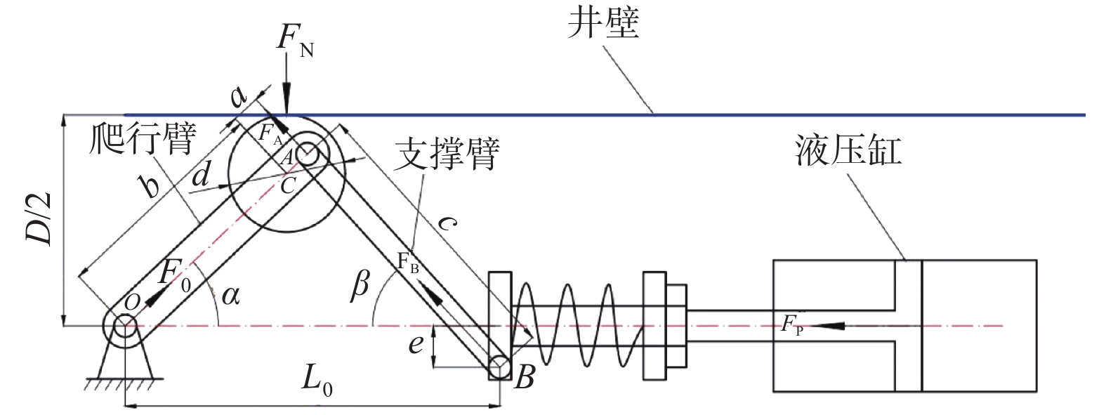
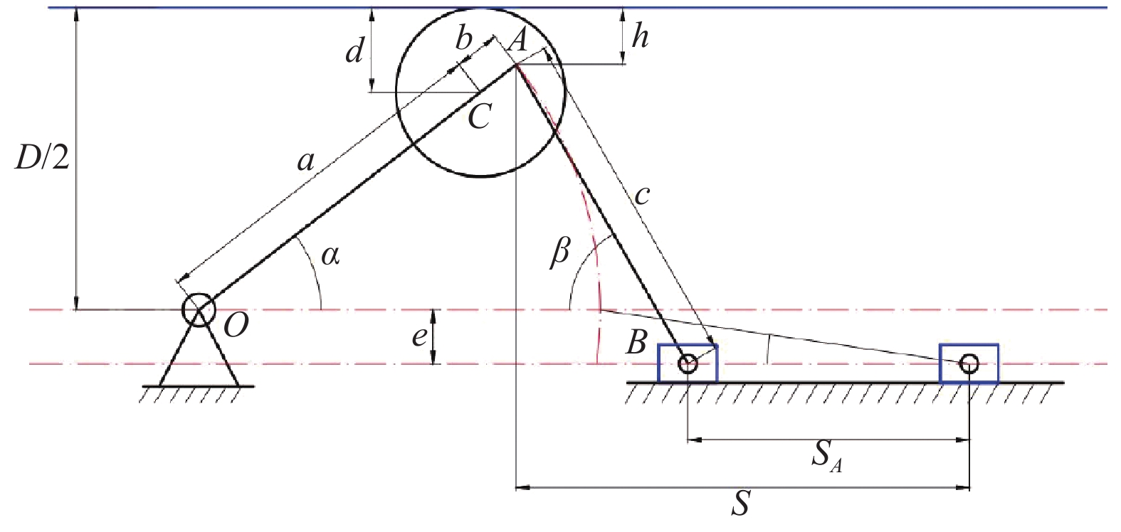
2.1 爬行臂和支撑臂受力分析
爬行臂和支撑臂的受力如图2所示(O为爬行臂铰接点,C为爬行轮中心)。
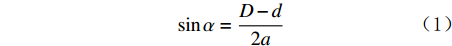
根据几何关系,可得[12]:
sinα=D−d2a (1) sinβ=D−d+2bsinα+2e2c (2) 式中:D为井筒直径,mm;a,b为爬行臂CA段和OC段的长度,爬行臂OA的长度为a+b,mm;c为支撑臂AB的长度,mm;d为爬行轮直径,mm;e为支撑臂铰接点与轴线的偏心距,mm;α为爬行臂转角,(°);β为支撑臂转角,(°)
对爬行臂和支撑臂进行受力分析,可得平衡方程:
{F0sinα+FBcosβ=FNF0cosα+FBsinβ=0 (3) 式中:F0为爬行臂正压力,N;FB为支撑臂B点推靠力,N;FN为爬行轮所受正压力,N。
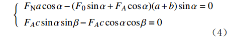
由此,得到支撑臂和爬行臂的力矩公式为:
{FNacosα−(F0sinα+FAcosα)(a+b)sinα=0FAcsinαsinβ−FAccosαcosβ=0 (4) 式中:FA为A点的推靠力,N。
由于支撑臂上A点和B点的力在各自方向上的分力大小相同、方向相反,联立式(3)和式(4)可得:
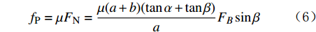
{F0cosα=FAsinα=FBsinβFAcosα+F0sinα=FNFNacosα−(a+b)FAsinα(cosαtanβ+sinα)=0 (5) 则爬行轮所受摩擦力fP为:
fP=μFN=μ(a+b)(tanα+tanβ)aFBsinβ (6) 式中:μ为爬行器与井壁的摩擦系数,理论上可取0.5;fP为爬行轮所受摩擦力,N。
取心器所需要的总推进力为6 000 N,爬行轮设计为2组,每组有3个爬行轮,则单个爬行轮所要达到的正压力为1 000 N。
2.2 爬行臂优化分析
在液压缸推力的作用下滑块移动,推动支撑臂伸出,爬行臂绕O点旋转,带动爬行轮压靠在井壁上(见图3)。爬行机构的基本性能参数是爬行轮的正压力及其工作效率。工作效率主要取决于支撑臂的伸出速度,支撑臂的伸出速度由滑块位移决定,爬行臂长度a+b、支撑臂长度c、爬行臂转角α和偏心距e等因素都会对其产生影响。将这4个影响因素确定为优化变量,建立爬行机构的优化设计函数。
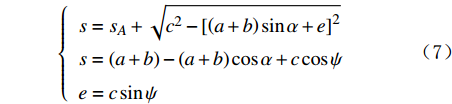
根据几何关系,可得:
{s=sA+√c2−[(a+b)sinα+e]2s=(a+b)−(a+b)cosα+ccosψe=csinψ (7) 式中:sA为滑块位移,mm;s为滑块右死点距铰接点A的水平距离,mm;
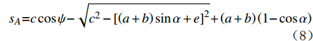
ψ 为支撑臂初始转角,(°)。化简式(7),可得滑块位移sA的计算式:
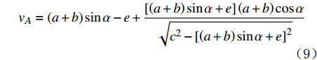
sA=ccosψ−√c2−[(a+b)sinα+e]2+(a+b)(1−cosα) (8) 式(8)对时间求导,可得支撑臂伸出速度vA的计算式:
vA=(a+b)sinα−e+[(a+b)sinα+e](a+b)cosα√c2−[(a+b)sinα+e]2 (9) 式中:vA为支撑臂的伸出速度,mm/s
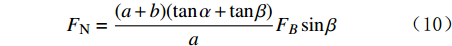
根据式(6),可得爬行轮所受正压力FN为:
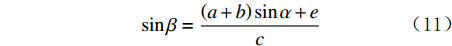
FN=(a+b)(tanα+tanβ)aFBsinβ (10) 根据几何关系及式(1)、式(2),可得:
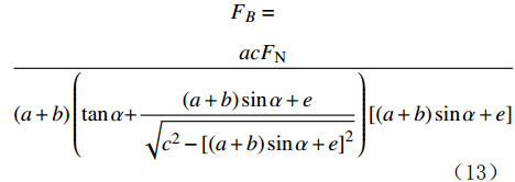
sinβ=(a+b)sinα+ec (11) tanβ=(a+b)sinα+e√c2−[(a+b)sinα+e]2 (12) 将式(11)、式(12)代入式(10),可得到支撑臂推靠力FB:
FB=acFN(a+b)(tanα+(a+b)sinα+e√c2−[(a+b)sinα+e]2)[(a+b)sinα+e] (13) 式(9)和式(13)即为爬行机构的多目标优化函数,利用正交试验分析法对其进行分析,可得到支撑臂及爬行臂有关参数的优化解。
影响支撑臂伸出速度和推靠力的因素包括爬行臂长度a+b、支撑臂长度c、爬行臂转角α和偏心距e。已知爬行轮直径为60 mm,取心器适用于ϕ200.0 mm的水平井,可以确定各影响因素的参数水平(见表1)。
表 1 正交试验各因素的水平Table 1. Factor level of the orthogonal test水平 因素 a/mm b/mm c/mm e/mm α/(°) 1 75 20 100 5 30 2 80 25 115 8 35 3 102 28 130 12 40 4 120 30 140 15 45 表 2 正交试验方案及结果Table 2. Plan and results of the orthogonal test序号 因素 vA/
(mm·s–1)FB/N a/mm b/mm c/mm e/mm α/(°) 1 75 20 100 5 30 43.034 1 476.282 2 75 25 115 8 35 49.923 948.763 3 75 28 130 12 40 54.784 760.183 4 75 30 140 15 45 59.831 613.171 5 80 20 115 12 45 59.442 546.541 6 80 25 100 15 40 53.611 401.823 7 80 28 140 5 35 57.392 1 244.544 8 80 30 130 8 30 47.480 1 326.465 9 102 20 130 15 35 55.684 817.832 10 102 25 140 12 30 52.055 1 222.991 11 102 28 100 8 45 102.036 29.503 12 102 30 115 5 40 80.807 473.042 13 120 20 140 8 40 82.741 673.195 14 120 25 130 5 45 98.571 404.759 15 120 28 115 15 30 60.058 582.237 16 120 30 100 12 35 78.109 143.874 为了确定上述各因素对试验指标的影响,将求解的指标进行极差计算,即可找出各因素的主次顺序及优化组合,结果见表3和表4。正交试验各指标的平均值用ki(i=1,2,3,4)表示,其中i表示每个变量的因素水平顺序,将各指标平均值进行极差处理。极差R表示目标量变化的最大范围,可以用来表征不同变量对指标值的影响程度。指标值越大,此变量对目标函数的影响程度越大,需要重点考虑;指标值越小,此变量对目标函数的影响越小,可优先满足其他指标后再进行考虑[13-14]。
表 3 支撑臂伸出速度极差分析结果Table 3. The extension speed range analysis of the supporting arm参数 不同因素水平对应的支撑臂伸出速度vA /(mm·s–1) a b c e α k1 51.799 60.225 69.197 69.951 50.657 k2 54.481 63.540 62.558 70.545 60.277 k3 72.645 68.568 64.130 61.098 67.985 k4 79.870 66.557 63.005 57.296 79.970 R 28.071 8.343 6.639 13.249 29.313 表 4 支撑臂推靠力极差分析结果Table 4. The push-the-bit force range analysis of the supporting arm参数 不同因素水平对应的支撑臂推靠力FB/N a b c e α k1 949.550 878.460 512.870 899.650 1 151.990 k2 879.325 744.580 637.650 744.480 788.750 k3 635.830 374.120 827.310 668.400 577.040 k4 451.000 638.910 938.470 603.750 398.490 R 498.550 504.340 425.600 295.900 753.500 根据多目标优化理论,对2个目标量vA和FB进行分析,得出各因素的影响程度:各因素对目标函数vA的影响程度从大到小的顺序为α,a,e,b和c;对目标函数FB的影响程度从大到小的顺序为α,b,a,c和e。比较2组目标函数的优化值,可首先确定α,a和b的优化解分别为45°,120 mm和30 mm。通过比较影响程度的大小,得到e的优化解为8 mm,根据爬行臂长度确定c的优化解为140 mm。
为了确定求得的优化解对爬行机构试验指标的影响,将优化解代入原目标函数,并与优化前各结构尺寸的试验指标进行对比,结果见表5。
表 5 优化前后试验指标对比Table 5. Comparison between test indicators before and after optimization优化前后 a/mm b/mm c/mm e/mm α/(°) vA/(mm·s–1) FB/N 优化前 75 20 100 5 30 43.034 1 259.222 80 25 115 8 35 52.829 893.596 102 28 130 12 40 72.393 554.946 120 30 140 15 45 92.284 339.869 优化后 120 30 140 8 45 99.060 408.230 从表5可以看出,根据正交试验结果优选出的结构尺寸可以降低支撑臂所需推靠力,提高支撑臂伸出速度,说明可以使用正交试验方法优化爬行机构的结构尺寸,优化结果满足要求。
2.3 爬行机构结构设计
根据爬行臂和支撑臂的优化设计结果,对爬行机构的各零部件进行设计、选型、强度校核和刚度校核,使用Solidworks软件对其进行建模和虚拟装配,得到了爬行机构的三维模型,如图4所示。
3. 结 论
1)根据页岩气井旋转式井壁取心器的工作要求,设计了一种由行星齿轮、锥齿轮组合传动的新型爬行机构,能够带动整个取心器行进。
2)根据机械动力学原理,建立了爬行机构正压力、支撑臂伸出速度、支撑臂推靠力与爬行臂及支撑臂结构尺寸的函数方程。
3)爬行臂转角对支撑臂伸出速度和推靠力影响最大。爬行臂转角优化后,可以降低支撑臂所需推靠力,提高支撑臂伸出速度,优化结果满足要求。
-
表 1 正交试验各因素的水平
Table 1 Factor level of the orthogonal test
水平 因素 a/mm b/mm c/mm e/mm α/(°) 1 75 20 100 5 30 2 80 25 115 8 35 3 102 28 130 12 40 4 120 30 140 15 45  下载: 导出CSV
表 2 正交试验方案及结果
Table 2 Plan and results of the orthogonal test
序号 因素 vA/
(mm·s–1)FB/N a/mm b/mm c/mm e/mm α/(°) 1 75 20 100 5 30 43.034 1 476.282 2 75 25 115 8 35 49.923 948.763 3 75 28 130 12 40 54.784 760.183 4 75 30 140 15 45 59.831 613.171 5 80 20 115 12 45 59.442 546.541 6 80 25 100 15 40 53.611 401.823 7 80 28 140 5 35 57.392 1 244.544 8 80 30 130 8 30 47.480 1 326.465 9 102 20 130 15 35 55.684 817.832 10 102 25 140 12 30 52.055 1 222.991 11 102 28 100 8 45 102.036 29.503 12 102 30 115 5 40 80.807 473.042 13 120 20 140 8 40 82.741 673.195 14 120 25 130 5 45 98.571 404.759 15 120 28 115 15 30 60.058 582.237 16 120 30 100 12 35 78.109 143.874
下载: 导出CSV
表 3 支撑臂伸出速度极差分析结果
Table 3 The extension speed range analysis of the supporting arm
参数 不同因素水平对应的支撑臂伸出速度vA /(mm·s–1) a b c e α k1 51.799 60.225 69.197 69.951 50.657 k2 54.481 63.540 62.558 70.545 60.277 k3 72.645 68.568 64.130 61.098 67.985 k4 79.870 66.557 63.005 57.296 79.970 R 28.071 8.343 6.639 13.249 29.313
下载: 导出CSV
表 4 支撑臂推靠力极差分析结果
Table 4 The push-the-bit force range analysis of the supporting arm
参数 不同因素水平对应的支撑臂推靠力FB/N a b c e α k1 949.550 878.460 512.870 899.650 1 151.990 k2 879.325 744.580 637.650 744.480 788.750 k3 635.830 374.120 827.310 668.400 577.040 k4 451.000 638.910 938.470 603.750 398.490 R 498.550 504.340 425.600 295.900 753.500
下载: 导出CSV
表 5 优化前后试验指标对比
Table 5 Comparison between test indicators before and after optimization
优化前后 a/mm b/mm c/mm e/mm α/(°) vA/(mm·s–1) FB/N 优化前 75 20 100 5 30 43.034 1 259.222 80 25 115 8 35 52.829 893.596 102 28 130 12 40 72.393 554.946 120 30 140 15 45 92.284 339.869 优化后 120 30 140 8 45 99.060 408.230
下载: 导出CSV
-
[1] 王建龙,冯冠雄,刘学松,等. 长宁页岩气超长水平段水平井钻井完井关键技术[J]. 石油钻探技术,2020,48(5):9–14. WANG Jianlong, FENG Guanxiong, LIU Xuesong, et al. Key technology for drilling and completion of shale gas horizontal wells with ultra-long horizontal sections in Changning Block[J]. Petroleum Drilling Techniques, 2020, 48(5): 9–14.
[2] 李传武,兰凯,杜小松,等. 川南页岩气水平井钻井技术难点与对策[J]. 石油钻探技术,2020,48(3):16–21. LI Chuanwu, LAN Kai, DU Xiaosong, et al. Difficulties and countermeasures in horizontal well drilling for shale gas in Southern Sichuan[J]. Petroleum Drilling Techniques, 2020, 48(3): 16–21.
[3] 张宇奇.旋转式井壁取心机器人的设计与研究[D].成都: 西华大学, 2019. ZHANG Yuqi. Design and research of rotary shaft core robot[D]. Chengdu: Xihua University, 2019.
[4] 张朝界.页岩气长水平段取芯爬行机器人机构设计与研究[D].成都: 西华大学, 2020. ZHANG Chaojie. Design and research on the mechanism of long horizontal shale gas coring crawling robot[D]. Chengdu: Xihua University, 2020.
[5] HALLUNDBÆK J. Well tractors for highly deviated and horizontal wells[J]. SPE 28871, 1994.
[6] 刘清友,李维国. Sondex水平井井下爬行工具介绍[J]. 国外测井技术,2008,23(5):57–59. LIU Qingyou, LI Weiguo. Introduction of sondex horizontal well downhole crawling tool[J]. World Well Logging Technology, 2008, 23(5): 57–59.
[7] HENDERSON B, HOPWOOD C, HAMILTON C, et al. Cost saving benefits of using a fully bi-directional tractor system[R]. SPE 65467, 2000.
[8] BUYERS M, FRASER S B. Reciprocating running tool: US06345669[P]. 2002-02-12.
[9] 高进伟, 刘猛, 李海凤. 水平井井下自适应爬行器的研制[J]. 石油机械, 2005, 33(增刊1): 100-104. GAO Jingwei, LIU Meng, LI Haifeng. Development of an adaptive crawler in horizontal wells[J]. China Petroleum Machinery, 2005, 33(supplement 1): 100-104.
[10] 周劲辉,张勇,李翠. 水平井自扶正式电缆牵引器的设计[J]. 石油机械,2015,43(2):79–82. ZHOU Jinghui, ZHANG Yong, LI Cui. Design of self-righting cable tractor in horizontal well[J]. China Petroleum Machinery, 2015, 43(2): 79–82.
[11] 唐德威,王新杰,邓宗全,等. 水平油井检测仪器拖动器[J]. 哈尔滨工业大学学报,2007,39(9):1395–1397. TANG Dewei, WANG Xinjie, DENG Zongquan, et al. Driver of horizontal oil well detecting instruments[J]. Journal of Harbin Institute of Technology, 2007, 39(9): 1395–1397.
[12] 张勇.水平井电缆牵引器的机械设计研究[D].北京: 中国石油大学(北京), 2016. ZHANG Yong. Research on mechanical design of cable tractor in horizontal wells[D]. Beijing: China University of Petroleum (Beijing), 2016.
[13] 姜立标,刘坚雄,程铖. 基于正交试验的矿用自卸车转向机构优化设计[J]. 中国机械工程,2013,24(15):2036–2041. JIANG Libiao, LIU Jianxiong, CHENG Cheng. Optimization design of mining dump truck steering mechanism based on orthogonal test[J]. China Mechanical Engineering, 2013, 24(15): 2036–2041.
[14] 邢相伟,彭彦平,庞桂兵,等. 基于正交试验法沾浆机浆拐结构的优化改进[J]. 大连工业大学学报,2015,34(2):153–156. XING Xiangwei, PENG Yanping, PANG Guibing, et al. Optimization of agitator structure of slurry mixer by orthogonal test method[J]. Journal of Dalian Polytechnic University, 2015, 34(2): 153–156.


计量
- 文章访问数: 713
- HTML全文浏览量: 319
- PDF下载量: 99